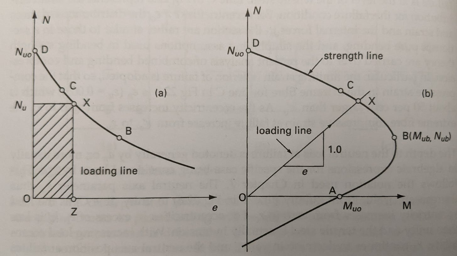
Columns are linear elements that primarily experience axial load. Unlike beam members which typically undergo pure bending with no axial load, columns often encounter bending in addition to the axial load.
As the bending moment increases, the axial capacity of the section begins to decrease. The bending moment can be thought of as the same axial load on the column with increasing eccentricity, e.
From the charts above, Point D is pure axial load with no bending.
Point C is often termed the decompression point, and is where the concrete section starts to go into tension on one face.1
Point B is where the balanced failure condition is met, meaning the concrete reaches its maximum compressive strain simultaneously with the steel reaching its yield strain.
Lastly, Point A is failure in pure bending, i.e. treating the section as a beam.
You can see from the example interaction diagram above that the curves between points are anything but linear. We could approximate the curve by drawing a straight line between points, but we can do better.
General method of analysis
We’ll be using a general method to generate the ULS interaction diagrams for a circular column. This applies to cross sections of arbitrary geometry and reinforcement arrangement, we’re going to look specifically at circles, since we’ll often be dealing with circular columns and piles for bridge design.
The process is relatively simple, but quite iterative, so should ideally be packaged into a script to run.
Note also that this analysis will be using a rectangular stress block like the one used in Australian Standards.
While points D through A mentioned above are useful to describe what’s going on in the section for various loading combinations, they are not needed to generate an interaction diagram.
We are essentially going to calculate the axial (N) and bending (M) capacity for various values of k2, ranging from k = ∞ (Point D) to k = 0 (Point A).
In practice, k does not need to be anywhere near ∞ to get accurate calculations and we can iterate over this range in a couple of seconds.
Rectangular stress block
To calculate the axial and bending capacities, first we’ll need to work out the area of concrete in compression. With the neutral axis known, this is a simple geometry exercise.3
The maximum width of the block:
Where r is the radius of the circular column.
From this we can calculate the angle subtended at the centre:
And then the area of concrete acted on by the rectangular stress block.
We want to generalise these parameters so they can be calculated for any value of k. Note that when the neutral axis is greater than the depth of section the area of concrete in compression will be the whole section.
With the angle subtended, we can also calculate the distance from the extreme compressive fibre to the centroid of the concrete in compression.
The resultant concrete compressive force:
Where the α and k factors are code-specific adjustments to the rectangular stress block. From AS 5100.5-2017:
Steel forces
With the ultimate compressive strain and neutral axis depth as inputs, we can calculate the strain at the position of any reinforcing bar using similar triangles.
With the strain at each steel position, we can calculate the force in the bar, limited by the yield stress of the bar.
For the bars in compression (ε > 0), we need to reduce the force slightly to account for the area of concrete we’ve already included in compression.
Alternatively, you could reduce the concrete compressive area above by the number of bars in compression.
Moments and forces
Now the forces in the steel are obtained, it’s a simple matter to obtain the axial and moment capacity of the section.
For the axial capacity, simply sum the tensile and compressive forces.
And for the moment capacity, we sum moments about the plastic centroid. For a circular column, this is simply the centre.
Next up
We’ll add the last piece of the puzzle, capacity reduction factors, and talk about turning this into a program, including the pros and cons of doing so.
Prior to Point C, the entire section is in compression.
We also need to include the neutral axis depth parameter, γ, in the depth of the stress block.


