

How to calculate epoxy mortar block geometry
How to calculate epoxy mortar block geometry
One of the more fiddly tasks associated with precast girders
Epoxy mortar blocks are often used with precast girders sitting atop bearings. The bearings will be installed with the top and bottom surfaces level (horizontal). The soffit of a precast girder on the other hand, is anything but level.
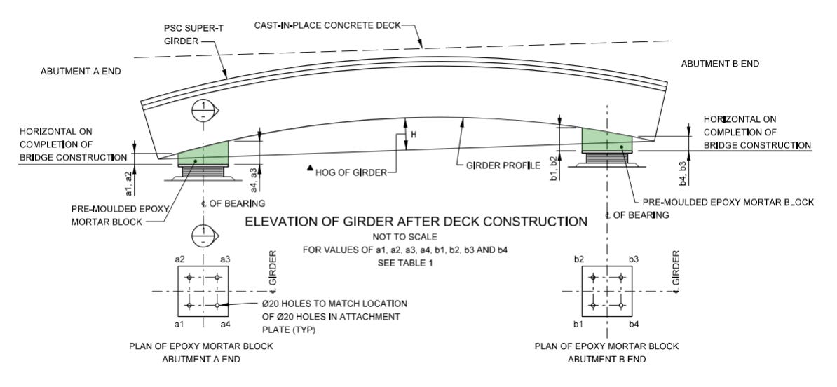
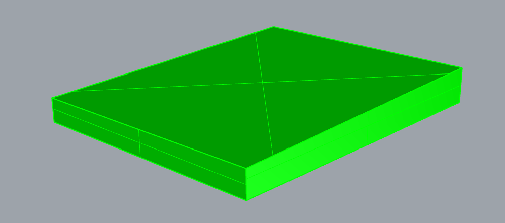
The epoxy mortar block is essentially a trapezoidal chunk of concrete with a level base and four different corner heights.
For an elastomeric bearing, the precast girder will have the epoxy mortar pad “buttered” to its soffit, with a steel top attachment plate on the underside of the epoxy mortar pad.
There are a variety of parameters which will affect the epoxy mortar block geometry:
Girder length
Girder hog
Bearing offset from end of precast girder
Top attachment plate geometry
Girder cross fall
Girder long fall
Of all these parameters, the one that is by far the most variable is girder hog. Hogs are typically higher than we calculate in design and will change the epoxy mortar block geometry considerably.
To calculate the epoxy mortar block geometry we’ll also need some reduced levels.
RL at the line of the bearing on the deck
RL at the bottom of the top attachment plate
Since most of the parameters are fixed except for girder hog, as designers we need a way of communicating with site what to do if hogs are of a certain value.
In theory we could provide a formula which says “input the hog and you get the geometry”.
I can already hear you laughing at the suggestion.
Instead, we typically work out a range of hog values, calculate the epoxy mortar block geometry and then allow linear interpolation if the hog is between values.
The result is a table like this:
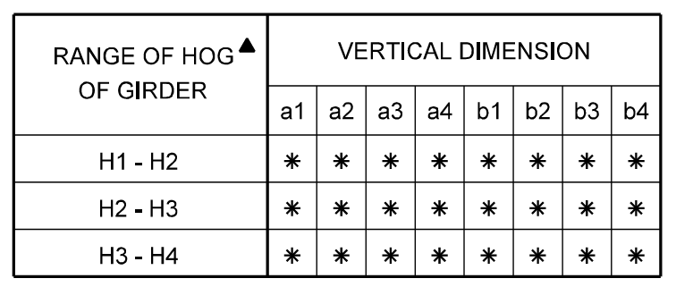
Where the values a1 through a4 are the corner dimensions of the epoxy mortar block at one end of the girder, and b1 through b4 are the dimensions at the other.
Equations for hog
Before we go much further, we need a refresher on the shape girder hogs take.
When a girder hogs, it deflects upwards in a parabolic arc. The hog at any position along the girder can be described as:

Where h is the hog of the girder at mid-span and x is the position along the girder, where x = 0 is at the left end, and x = L is at the right end. L is the length of the girder.
Taking the first derivative of this equation, we now have the slope at any position along the girder.

Determining hog range
The next step is to determine the hog range we wish to specify on the drawings. Our base for this is the hog we’ve calculated at transfer.
There are a couple of ways to select hog ranges. I like to use a hybrid of two.
The first is relatively simple. Take your calculated hog, increase it by 35% and decrease it by 35%. That’s it.
The second is a little more complicated. We first need to calculate how much hog would have to increase or decrease to create a change of 1 mm in the epoxy mortar block. That is, a 1 mm change between a1 and a4 or a2 and a3, or b1 and b4 or b2 and b3.
This hog value we calculate we’ll use as a step increment for the range we’ll present.
To calculate this we only need the slope. Put another way, the slope can be approximated by the following:

Where l is the length of the top attachment plate. Substituting this in to our slope equation and rearranging for h:

We only care about this value in one region along the girder though - the region above the top attachment plate. We can approximate this by substituting for x the coordinate of the centre of the bearing. For example, with a 400 mm offset from the end of the girder to the bearing centreline, you’d use a value of x = 400.
Using the above we can now develop a list of hogs we wish to calculate epoxy mortar block values for.
For example, consider a beam with the following properties:


This would result in the following hog values:
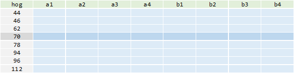
We’re going to populate the table above with a1 through b4 values. For hogs which lie between the range we’ve provided, you can linearly interpolate the epoxy mortar block thickness values.
Average epoxy mortar block thickness
We’re now going to calculate epoxy mortar block dimensions for each of the hogs we determined above. The first step is to determine the average thickness of the epoxy mortar block. That is, the thickness at the centre of the bearing, or more simply, the average of the four corners.
For example, the average thickness of the epoxy mortar block at the left-hand side of the beam:
Where all dimensions are in the same units,


Hog values are determined using our parabolic equation above and account for the wet deck deflection, where:


Corner thicknesses
Now we have the average thickness of the epoxy mortar block, we can calculate the four corner dimensions by considering the hog, cross fall, long fall and top attachment plate dimensions.

Where CF and LF are the cross falls and long falls of the girder as a decimal and

We can calculate the other 3 corners in a similar way.


The b values are mirrored:


For those playing along at home, I’ve used the following data:


Which results in the following table:

Vertical curves
There’s one final adjustment we need to make to these numbers. Do you know what big assumption we’ve made so far?
We’re assuming the minimum deck thickness will occur at mid-span.
Now while this will be true most of the time, it depends on the vertical curve of the road geometry.
Broadly, we have three scenarios which could occur with the road geometry.
No vertical curve
With no vertical curve the road profile is flat. There is still a longitudinal grade, but no curvature.
In this case, the minimum deck thickness will always occur at mid-span as the precast girder will curve upwards.
Where there is no vertical curve, the corner thicknesses above can be used unadjusted.

Sag vertical curve
Similarly, where the road profile sags, the minimum thickness will be at the mid-span as calculated.

Summit vertical curve
The road profile ‘crests’ in a similar fashion to the precast girder hog. In this scenario, the minimum deck thickness will occur at mid-span only when the residual hog (hog including wet deck deflection) is greater than the equivalent hog of the road profile.
For example if our road profile has a ‘hog’ of 50 mm and our precast girder has a residual hog of 70 mm:
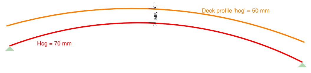
Whereas when the hog is less than the road profile, we’ll get a minimum deck thickness at the ends.

Which the calculations above don’t allow for.
The fix is fairly simple though. For all those hog ranges which are below the ‘hog’ of the road curvature, we need to reduce the thickness of corners
The amount that we need to reduce them:

There are a few different ways you can determine the deck profile ‘hog’, the subject of a future article I’m sure.
Using a deck profile hog of 40 mm, we get the following adjusted table.
